What you’ll learn
- 1Apply Ohm’s law and the voltage-divider rule to a real circuit.
- 2Rearrange the divider formula to solve for an unknown resistor.
- 3Convert ADC readings to voltage and estimate measurement accuracy.
- 4Handle edge cases (open circuit, short circuit) in code.
- 5Present a measurement professionally with units and formatting.
- Ohm’s law
- U = R · I — voltage equals resistance times current.
- Series circuit
- Components connected one after another; the same current flows through all of them.
- Reference resistor
- The known resistor (R_known) used to compare against the unknown one.
- Resolution
- The smallest change an instrument can detect. The Uno ADC: 5 V / 1023 ≈ 4.9 mV.
- Tolerance
- How far a real resistor may differ from its printed value (gold band = ±5 %).
Required equipment
| Component | Qty | Purpose |
|---|---|---|
| Arduino Uno | 1 | Microcontroller |
| Known resistor (e.g. 1 kΩ) | 1 | Reference for the voltage divider |
| Unknown resistors | several | Components to measure |
| Breadboard + jumper wires | 1 set | Component connection |
| USB cable | 1 | Connection to computer |
| Processing IDE | 1 | Display |
Voltage Divider & Ohm’s Law
Two resistors in series share the 5 V supply. The voltage at the midpoint depends on their ratio — so if we know one resistor and measure the voltage, we can calculate the other.
analogRead = round(1.563 / 5 × 10²³) = 320
R_x = 1.00 kΩ × (5 / 1.564 − 1) = 2.20 kΩ
Try R_x = 1 MΩ with R_known = 1 kΩ: the voltage is so small that one ADC step is a huge change in resistance. Accuracy is best when R_x ≈ R_known.
Step 1 — Circuit Setup
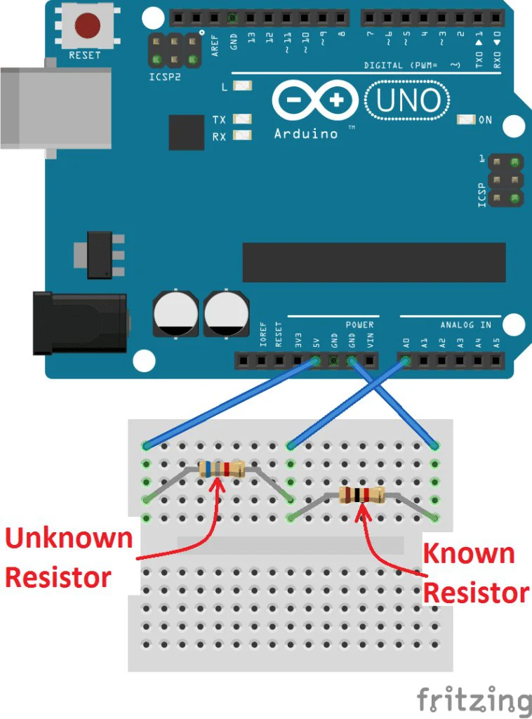
| Connection | Description |
|---|---|
| R_x (unknown) | Between 5V and A0 |
| R_known (e.g. 1 kΩ) | Between A0 and GND |
| A0 | Junction between R_x and R_known |
Step 2 — Arduino Code
const int analogPin = A0;
const float Vin = 5.0;
const float R_known = 1000.0;     // known resistor in ohms

void setup() {
  Serial.begin(9600);
}

void loop() {
  int raw = analogRead(analogPin);
  if (raw == 0) {
    Serial.println(-1);           // nothing connected (open circuit)
  } else {
    float Vout = raw * Vin / 1023.0;
    float Rx = R_known * (Vin / Vout - 1);
    Serial.println(Rx);           // send resistance to Processing
  }
  delay(500);
}vconst typo and added a guard for an open circuit (division by zero).Step 3 — Processing Code
import processing.serial.*;

Serial myPort;
float resistance = 0;

void setup() {
  size(400, 200);
  myPort = new Serial(this, Serial.list()[0], 9600);
  myPort.bufferUntil('\n');
}

void draw() {
  background(255);
  fill(0);
  textSize(20);
  text("Measured Resistance:", 50, 80);
  if (resistance < 0) text("no resistor", 50, 120);
  else                text(nf(resistance, 1, 2) + " \u03A9", 50, 120);
}

void serialEvent(Serial p) {
  String val = p.readStringUntil('\n');
  if (val != null) resistance = float(trim(val));
}- ▸Arduino reads the voltage at the midpoint of the divider.
- ▸It calculates the unknown resistance with the rearranged formula.
- ▸The value is sent over serial to Processing.
- ▸Processing displays it in real time with units.
Student tasks
Troubleshooting
| Problem | Likely cause | Fix |
|---|---|---|
| Shows “no resistor” or a huge value | R_x not connected / open circuit | Check both legs of R_x are in the right rows. |
| Shows ≈ 0 Ω | R_x shorted (both legs in the same row) | Place each leg in a different row. |
| Reading is inaccurate | R_known value in code is wrong | Measure R_known and update the constant. |
| Fluctuating values | Poor breadboard contact | Average 10 readings; press parts in firmly. |
Exercises
Derive the formula
Starting from V_A0 = V_in · R_known / (R_x + R_known), show step by step that R_x = R_known · (V_in / V_A0 − 1).
From reading to ohms
With R_known = 1 kΩ, Arduino reads raw = 310. Calculate V_A0 and R_x. Which standard resistor is it probably? (1 kΩ, 2.2 kΩ, 3.3 kΩ, 4.7 kΩ)
Debug the textbook
The first edition of this handbook said: “R1 (known) between 5V and A0, R2 (unknown) between A0 and GND” but used the formula R2 = R1 · (Vin/Vout − 1). Using R1 = 1 kΩ and a real unknown of 2.2 kΩ, calculate what the meter would display. What is the correct formula for that wiring?
Colour by range
Colour the displayed value: green below 1 kΩ, orange 1 kΩ–10 kΩ, purple above 10 kΩ. Also display large values in kΩ (e.g. 4.70 kΩ).
String label;
if (resistance < 1000) {
  fill(0, 170, 80);
  label = nf(resistance, 1, 1) + " \u03A9";
} else {
  fill(resistance < 10000 ? color(255, 140, 0) : color(130, 60, 200));
  label = nf(resistance / 1000.0, 1, 2) + " k\u03A9";
}
textSize(36);
text(label, 50, 140);Analog gauge
Draw a semicircular gauge (like an old multimeter) from 0 to 10 kΩ with tick marks every 1 kΩ and a needle pointing at the current value.
arc(cx, cy, d, d, PI, TWO_PI). Map resistance to an angle between PI and TWO_PI.void drawGauge(float value, float maxValue) {
float cx = width / 2, cy = height - 30, r = 150;
noFill();
stroke(40);
strokeWeight(3);
arc(cx, cy, r * 2, r * 2, PI, TWO_PI);
strokeWeight(1);
for (int i = 0; i <= 10; i++) { // ticks
float a = map(i, 0, 10, PI, TWO_PI);
line(cx + cos(a) * (r - 12), cy + sin(a) * (r - 12),
cx + cos(a) * r, cy + sin(a) * r);
}
float a = map(constrain(value, 0, maxValue), 0, maxValue, PI, TWO_PI);
stroke(220, 40, 40); // needle
strokeWeight(4);
line(cx, cy, cx + cos(a) * (r - 20), cy + sin(a) * (r - 20));
}Accuracy investigation
Measure at least 8 resistors (100 Ω … 100 kΩ) with your Arduino meter and a real multimeter. Calculate the percentage error for each. Plot error vs. resistance. When is your meter most accurate, and why? Propose an improvement (e.g. auto-ranging).
Self-check quiz
- Q01
Ohm’s law states…
- Q02
In this circuit, if R_x gets bigger, V_A0…
- Q03
If R_x = R_known, the reading on A0 is about…
- Q04
Why does the code check raw == 0?
- Q05
What does nf(1234.5678, 1, 2) return?
Real world & extensions
- +Automatic resistor classification by range
- +An analog-style gauge in Processing
- +Show the resistor colour code next to the measured value
- +Measure potentiometers and watch the value change
- +Log measurements to CSV and compare with tolerances
- +Auto-ranging with several known resistors
| Subject | Connection |
|---|---|
| Physics | Ohm’s law, series circuits, voltage division |
| Mathematics | Rearranging equations, error and percentages |
| Technology | Measurement instruments, calibration |
Reflection & conclusion
How does a commercial multimeter measure resistance? Is it similar to your circuit?
What sources of error did you notice? Which could you reduce?
Why is it important that a formula matches the actual circuit? Where else in science does this matter?
This project introduced electrical measurement, voltage dividers and real-time display. By combining the Arduino Uno with Processing you built a working ohm meter, practised rearranging formulas, and learned to question whether a formula really matches the circuit in front of you — a core skill for every engineer.