What you’ll learn
- 1Explain how the resistance of an LDR changes with light.
- 2Build a voltage divider and calculate its output voltage.
- 3Convert between voltage and the 10-bit ADC value (0–1023).
- 4Visualize a single sensor value as text, a bar and a background colour.
- 5Calibrate a sensor by measuring its minimum and maximum in real conditions.
- LDR / photoresistor
- A resistor whose resistance falls when light shines on it (≈ 1 MΩ in darkness, ≈ 1 kΩ in bright light).
- Voltage divider
- Two resistors in series; the voltage in the middle depends on their ratio.
- ADC
- Analog-to-Digital Converter: turns 0–5 V into a number 0–1023 (10-bit) on the Uno.
- analogRead()
- Arduino function that reads an analog pin and returns 0–1023.
- Calibration
- Measuring real minimum and maximum values so your scale fits reality.
Required equipment
| Component | Qty | Purpose |
|---|---|---|
| Arduino Uno | 1 | Microcontroller |
| Photoresistor (LDR) | 1 | Light sensing |
| 10 kΩ resistor | 1 | Voltage divider |
| Breadboard | 1 | Component connection |
| Jumper wires | ~5 | Component connection |
| USB cable | 1 | Connection to computer |
| Processing IDE | 1 | Data visualization |
Theoretical Background
How does a photoresistor work?
An LDR (Light Dependent Resistor) is made of a semiconductor. Light gives its electrons enough energy to conduct, so in bright light the resistance decreases; in darkness it increases.
The voltage divider
Arduino can’t measure resistance directly — only voltage. So we put the LDR in series with a fixed 10 kΩ resistor. The voltage at the junction (connected to A0) changes with light.
Exercise 1 — Circuit Setup & Arduino Code
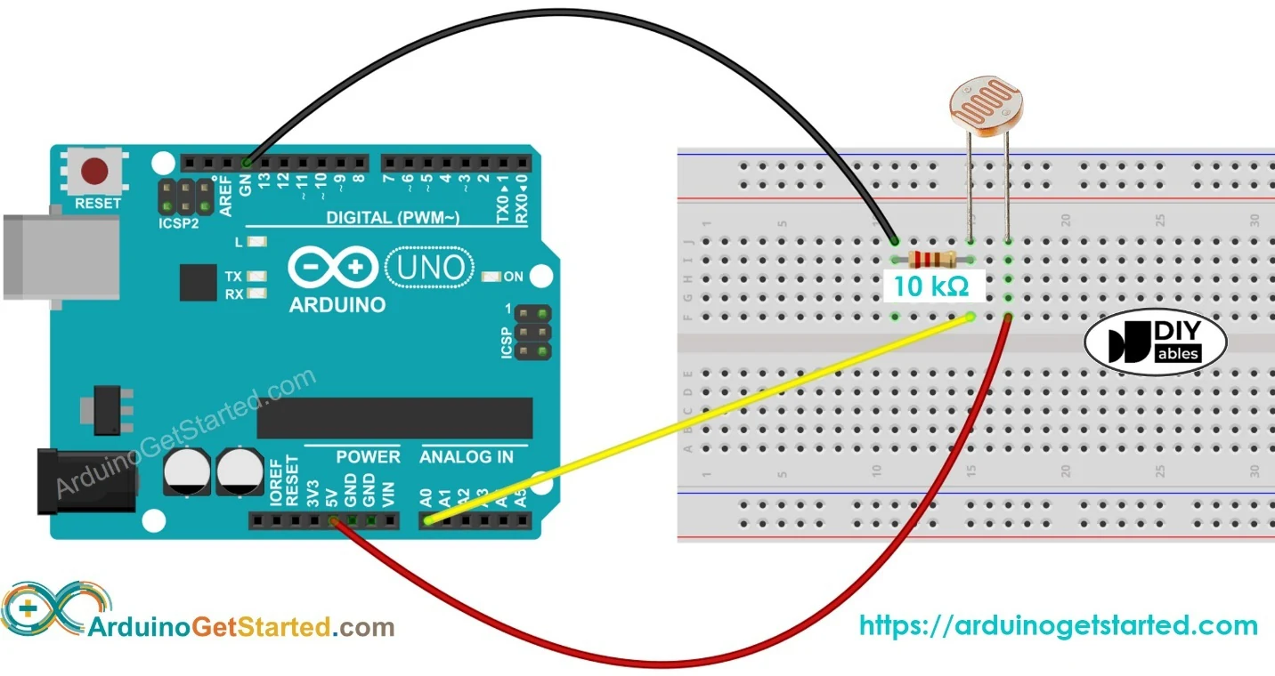
| Component | Connects to |
|---|---|
| LDR (leg 1) | 5V |
| LDR (leg 2) | A0 and 10 kΩ resistor (leg 1) |
| 10 kΩ resistor (leg 2) | GND |
const int sensorPin = A0;

void setup() {
  Serial.begin(9600);
}

void loop() {
  int lightValue = analogRead(sensorPin);   // 0 (dark) … 1023 (bright)
  Serial.println(lightValue);
  delay(200);
}Exercise 2 — Processing Visualization
Start simple with a text display, then upgrade to the robust serialEvent() version with a bar.
import processing.serial.*;

Serial myPort;
int lightLevel = 0;

void setup() {
  size(400, 200);
  myPort = new Serial(this, Serial.list()[0], 9600);
}

void draw() {
  background(255);
  fill(0);
  textSize(20);
  text("Light Intensity: " + lightLevel, 50, 100);

  if (myPort.available() > 0) {
    String val = myPort.readStringUntil('\n');
    if (val != null) lightLevel = int(trim(val));
  }
}import processing.serial.*;
Serial myPort;
int lightLevel = 0;
void setup() {
size(400, 200);
myPort = new Serial(this, Serial.list()[0], 9600);
myPort.bufferUntil('\n');
}
void draw() {
background(255);
fill(0);
textSize(20);
text("Light Intensity: " + lightLevel, 50, 50);
fill(0, 100, 255);
rect(50, 100, map(lightLevel, 0, 1023, 0, 300), 30);
}
void serialEvent(Serial p) {
String val = p.readStringUntil('\n');
if (val != null) {
val = trim(val);
if (val.matches("\\d+")) lightLevel = int(val);
}
}background(255) with background(map(lightLevel, 0, 1023, 0, 255)); — the window now gets darker when the room gets darker.Student tasks
Troubleshooting
| Problem | Likely cause | Fix |
|---|---|---|
| Value stays at 0 | LDR not connected or open circuit | Check the LDR leg goes to 5V and the junction to A0. |
| Value stays at 1023 | Resistor missing or GND not connected | Check the 10 kΩ resistor goes from A0 to GND. |
| Unstable readings | Poor breadboard contact or flickering lights | Press components in firmly; average several readings. |
| Range is small (e.g. 400–700) | Fixed resistor doesn’t match the LDR | Try 4.7 kΩ or 22 kΩ, or calibrate with map(). |
Exercises
Voltage divider practice
With R_fixed = 10 kΩ and 5 V supply, calculate V_A0 and the expected analogRead() value when the LDR is (a) 1 kΩ (bright), (b) 10 kΩ (normal room), (c) 100 kΩ (dark).
Swap the parts
What happens to the readings if you swap the LDR and the 10 kΩ resistor (LDR now between A0 and GND)?
Automatic night-light
Add an LED (pin 9 + 220 Ω). Turn it on when the reading drops below a threshold of your choice and off when it is brighter. Print the state to the Serial Monitor.
const int sensorPin = A0;
const int ledPin = 9;
const int THRESHOLD = 300;

void setup() {
  Serial.begin(9600);
  pinMode(ledPin, OUTPUT);
}

void loop() {
  int light = analogRead(sensorPin);
  bool dark = light < THRESHOLD;
  digitalWrite(ledPin, dark ? HIGH : LOW);
  Serial.println(light);
  delay(200);
}Smooth dimming with PWM
Instead of on/off, make the LED on pin 9 get brighter as the room gets darker, using analogWrite() (0–255).
map(light, 0, 1023, 255, 0) — note the reversed output range.void loop() {
int light = analogRead(A0);
int brightness = map(light, 0, 1023, 255, 0);
analogWrite(9, constrain(brightness, 0, 255));
Serial.println(light);
delay(50);
}Calibrate with min/max
Your sensor never reaches 0 or 1023. Make Processing remember the smallest and largest values it has seen and map the bar between those, so it always uses the full width. Press R to reset calibration.
int lo = 1023, hi = 0;

// in serialEvent(), after lightLevel is updated:
lo = min(lo, lightLevel);
hi = max(hi, lightLevel);

// in draw():
float w = (hi > lo) ? map(lightLevel, lo, hi, 0, 300) : 0;
rect(50, 100, w, 30);
text("calibrated: " + lo + " – " + hi, 50, 170);

void keyPressed() {
  if (key == 'r' || key == 'R') { lo = 1023; hi = 0; }
}Sunrise logger
Design an experiment that measures how light levels change near a window during a whole school day. Log a value every minute with a timestamp, then plot a graph. At what time is your classroom brightest? Does it depend on the weather?
delay(60000) or millis() on Arduino (or a timer in Processing), log with PrintWriter, and plot in Processing or a spreadsheet. Discuss clouds, blinds, artificial lighting, and the direction the window faces.Self-check quiz
- Q01
In bright light, an LDR’s resistance…
- Q02
What range does analogRead() return on the Arduino Uno?
- Q03
Why do we need the fixed 10 kΩ resistor?
- Q04
An analog reading of 512 corresponds to roughly…
- Q05
The reading is always 1023. The most likely cause is:
Real world & extensions
- +Add an LED that automatically reacts to light intensity
- +Build an automatic night-light system
- +Use two LDRs for directional light detection (sun tracker)
- +Send the data over WiFi for remote monitoring
- +Build a smart-home lighting prototype
- +Show data on an OLED or LCD screen
- +Log light intensity for long-term analysis
| Subject | Connection |
|---|---|
| Physics | Semiconductors, resistance, voltage dividers |
| Mathematics | Ratios, linear scaling, non-linear curves |
| Biology | Photosynthesis and daylight cycles |
| Computer Science | Analog input, data validation |
Reflection & conclusion
Which devices you own adjust themselves to light? How do you think they do it?
The LDR response is not linear. Why might that matter when you build a “lux meter”?
How could automatic lighting reduce your school’s energy use?
You learned how analog sensors and voltage dividers work, and how to turn a changing resistance into a live visualization. By combining the Arduino Uno with Processing you built an interactive light meter — the same idea behind auto-brightness screens and smart street lighting.