What you’ll learn
- 1Identify the main parts of the Arduino Uno board (USB, digital pins, analog pins, GND, 5V, reset button, ATmega328P).
- 2Explain how the rows and rails of a breadboard are connected inside.
- 3Write, verify and upload a sketch using
setup(),loop(),pinMode(),digitalWrite()anddelay(). - 4Wire an LED safely with a current-limiting resistor and calculate a suitable resistor value.
- 5Follow a systematic workflow: schematic → simulation → real wiring → upload → test.
- Microcontroller
- A tiny computer on a single chip that reads inputs and controls outputs. On the Uno it is the ATmega328P.
- Sketch
- The name for an Arduino (or Processing) program.
- Digital pin
- A pin that is either HIGH (5 V) or LOW (0 V). The Uno has pins 0–13.
- Analog pin
- A pin (A0–A5) that can measure a voltage between 0 and 5 V as a number 0–1023.
- GND (ground)
- The 0 V reference point. Every circuit needs a path back to GND.
- Anode / Cathode
- The + (longer leg) and − (shorter leg, flat side) of an LED.
- Resistor
- A component that limits current. Measured in ohms (Ω).
- Breadboard
- A reusable board for building circuits without soldering.
Required equipment
| Component | Qty | Purpose |
|---|---|---|
| Arduino Uno | 1 | Main development board |
| USB cable | 1 | Connection to computer and program upload |
| Breadboard | 1 | Quick connection without soldering |
| LED diode | 1–3 | Visual indicator of program execution |
| 220 Ω resistor | 1–3 | Current limiting for the LED |
| Push button | 1 | Input for the advanced tasks |
| Jumper wires | ~6 | Connecting components |
| Arduino IDE | 1 | Writing and uploading programs |
| Tinkercad or Circuit Designer | 1 | Circuit simulation and verification |
What is Arduino?
Arduino is a hardware and software platform built around a microcontroller. A small board can read signals from sensors, process them, and then control LEDs, motors, relays, displays or other devices.
Thanks to simple wiring, a huge number of examples and extensive library support, Arduino is ideal for beginners as well as for rapid prototyping in school and project work.
Why the Arduino Uno?
The Uno is the most common first board: stable, well documented and easy to use. It has enough input/output pins for school experiments without unnecessary complexity. Once you know the Uno, moving to a Nano, Mega or ESP32 is easy.
Anatomy of the Uno
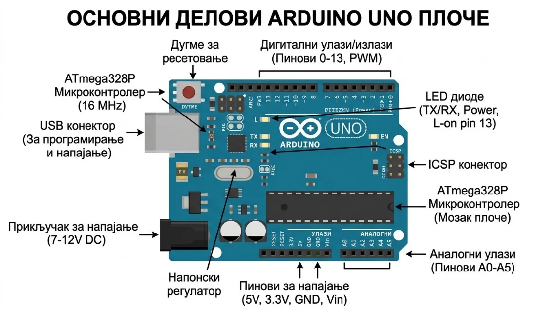
| Part | What it does |
|---|---|
| USB connector | Connects to the computer — power + program upload |
| Digital pins 0–13 | Digital input and output (HIGH / LOW) |
| Analog pins A0–A5 | Read analog sensor values (0–1023) |
| GND | Ground — the negative reference |
| 5V and 3.3V | Power supply pins for components |
| Built-in LED | Connected to pin 13 — perfect for the first test |
| Reset button | Restarts your program from the beginning |
| ATmega328P | The microcontroller chip — the processor of the board |
Breadboard, Resistors & LEDs
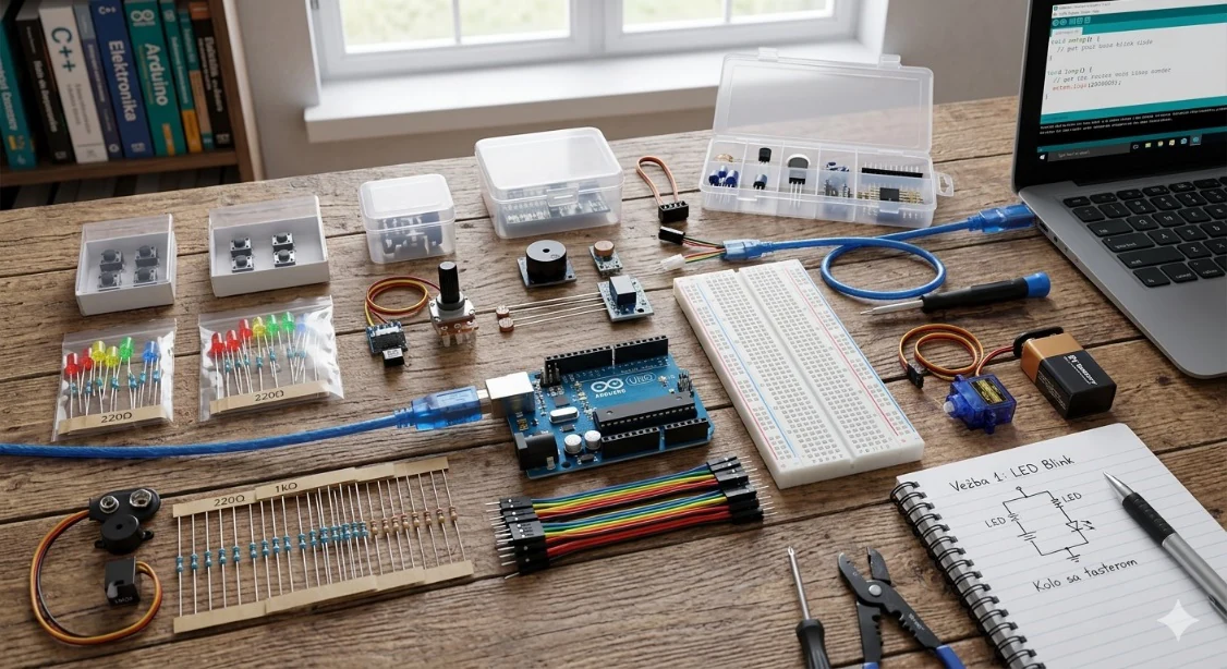
A breadboard lets you connect components without soldering, so you can change connections, test ideas and re-verify circuits quickly. Inside, each short row of 5 holes is connected; the long rails along the edges are usually used for 5V and GND.
A resistor limits current. An LED has almost no resistance of its own, so without a resistor it would draw too much current and burn out — or damage the Arduino pin.
How big should the resistor be?
Use Ohm’s law. The resistor “uses up” the voltage the LED doesn’t need. With a 5 V pin, a red LED that drops about 2 V, and a safe current of about 15 mA:
next standard (E12) ≥ ideal → 220 Ω
Always round up to the next available value — a slightly larger resistor means slightly less current, which is safe.
Arduino IDE, Tinkercad & Circuit Designer
Programs for Arduino are usually written in the Arduino IDE: this is where code is written, checked for errors and uploaded to the board. Tinkercad and Circuit Designer let you plan and simulate a circuit before building it for real.
- ▸writing and editing programs (sketches),
- ▸uploading programs to the Arduino board,
- ▸monitoring program execution via the Serial Monitor,
- ▸adding libraries for sensors and other components.
The IDE is free on the official Arduino website. After installing, select the correct board type and COM port, then upload.
Sensors & actuators you will meet later
| Sensor / Actuator | Type | Used in |
|---|---|---|
| DHT11 | Temperature & humidity sensor | Project 1 |
| LDR (photoresistor) | Light sensor | Project 2 |
| HC-SR04 | Ultrasonic distance sensor | Project 3 |
| SG90 servo motor | Position actuator | Project 3 |
| Relay module | Electrical switch (actuator) | Project 5 |
| Soil moisture sensor | Capacitive sensor | Project 5 |
Lab 1 — First Upload: Blink
This lab checks that the board is connected, the right COM port is selected and a program uploads successfully. We use the built-in LED on pin 13, so no external circuit is needed — the best possible first test.
const int ledPin = 13;      // built-in LED

void setup() {
  pinMode(ledPin, OUTPUT);  // runs once
}

void loop() {               // repeats forever
  digitalWrite(ledPin, HIGH);
  delay(1000);
  digitalWrite(ledPin, LOW);
  delay(1000);
}| Command | Explanation |
|---|---|
const int ledPin = 13; | Defines the pin number where the LED is connected. |
setup() | Runs once at the start of the program. |
pinMode(ledPin, OUTPUT); | Sets the pin as an output. |
loop() | Repeats indefinitely while the board is powered. |
digitalWrite(ledPin, HIGH/LOW); | Turns the LED on (HIGH = 5 V) or off (LOW = 0 V). |
delay(1000); | Pauses execution for 1000 milliseconds = 1 second. |
How to upload
- 01Open the Arduino IDE.
- 02Go to Tools → Board → Arduino Uno.
- 03Go to Tools → Port and select the correct COM port.
- 04Click Upload (the → arrow icon).
- 05The built-in LED should start blinking once per second.
Lab 2 — An External LED on a Breadboard
Now move from the built-in LED to an external one and build a real circuit for the first time. Notice how the schematic, the physical wiring and the program connect.
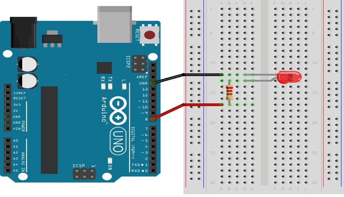
| Arduino Uno | Component | Connection |
|---|---|---|
| Pin 8 | LED anode (+) | Through a 220 Ω resistor |
| GND | LED cathode (−) | Directly to ground |
const int ledPin = 8;

void setup() {
  pinMode(ledPin, OUTPUT);
}

void loop() {
  digitalWrite(ledPin, HIGH);
  delay(500);
  digitalWrite(ledPin, LOW);
  delay(500);
}
The program turns the LED on pin 8 on, waits half a second (500 ms), turns it off, waits again — and repeats forever.
Student tasks
Troubleshooting
| Problem | Likely cause | Fix |
|---|---|---|
| Upload fails / “port not found” | Wrong COM port or board selected | Tools → Port: pick the port that appears when you plug the board in. |
| LED never lights | LED inserted backwards | Turn the LED around: long leg towards the resistor/pin. |
| LED lights but is very dim | Resistor too large (e.g. 10 kΩ) | Check the colour bands: 220 Ω is red-red-brown. |
| Nothing changes after editing | Code verified but not uploaded | Click Upload, not only Verify. |
Exercises
Predict the rhythm
Without running it, describe exactly what the LED does with this loop(). How many times does it flash per minute?
void loop() {
  digitalWrite(8, HIGH);
  delay(200);
  digitalWrite(8, LOW);
  delay(800);
}Choose the resistor
A blue LED needs about 3.0 V and should run at 10 mA. The Arduino pin gives 5 V. Calculate the ideal resistor, then choose a real value from this list: 100 Ω, 150 Ω, 220 Ω, 330 Ω, 1 kΩ.
SOS beacon
Program the external LED to blink SOS in Morse code: three short (200 ms), three long (600 ms), three short — then a 2-second pause. Use a helper function so you don’t repeat yourself.
void flash(int ms) that turns the LED on for ms, then off for 200 ms. Call it inside for loops.const int ledPin = 8;
void flash(int ms) {
digitalWrite(ledPin, HIGH);
delay(ms);
digitalWrite(ledPin, LOW);
delay(200);
}
void setup() {
pinMode(ledPin, OUTPUT);
}
void loop() {
for (int i = 0; i < 3; i++) flash(200); // S
for (int i = 0; i < 3; i++) flash(600); // O
for (int i = 0; i < 3; i++) flash(200); // S
delay(2000);
}Find three bugs
This sketch should blink an LED on pin 8 but it does not even compile — and even when it compiles, the LED stays dark. Find all three problems.
const int ledPin = 8

void setup() {
  pinMode(ledPin, INPUT);
}

void loop() {
  digitalWrite(ledPin, HIGH);
  delay(500);
  digitalWrite(ledpin, LOW);
  delay(500);
}const int ledPin = 8. 2) pinMode must be OUTPUT, not INPUT. 3) ledpin ≠ ledPin — names are case-sensitive.Push-button lamp
Add a push button between pin 2 and GND. The LED on pin 8 should be ON only while the button is held down. Use the internal pull-up resistor.
- 01Place the button across the middle gap of the breadboard.
- 02Connect one side to pin 2 and the other side to GND.
- 03In
setup()usepinMode(2, INPUT_PULLUP);. - 04Remember: with a pull-up, the pin reads LOW when pressed.
const int ledPin = 8;
const int buttonPin = 2;

void setup() {
  pinMode(ledPin, OUTPUT);
  pinMode(buttonPin, INPUT_PULLUP);
}

void loop() {
  bool pressed = digitalRead(buttonPin) == LOW;
  digitalWrite(ledPin, pressed ? HIGH : LOW);
}Traffic light controller
Build a traffic light with red (pin 10), yellow (pin 9) and green (pin 8) LEDs, each with its own 220 Ω resistor. Sequence: green 4 s → yellow 1 s → red 4 s → red + yellow 1 s → repeat. Extension: add a pedestrian button that shortens the green phase.
void lights(bool r, bool y, bool g, int ms) that sets all three LEDs and then waits.const int RED = 10, YELLOW = 9, GREEN = 8;
void lights(bool r, bool y, bool g, int ms) {
digitalWrite(RED, r);
digitalWrite(YELLOW, y);
digitalWrite(GREEN, g);
delay(ms);
}
void setup() {
pinMode(RED, OUTPUT);
pinMode(YELLOW, OUTPUT);
pinMode(GREEN, OUTPUT);
}
void loop() {
lights(0, 0, 1, 4000); // green
lights(0, 1, 0, 1000); // yellow
lights(1, 0, 0, 4000); // red
lights(1, 1, 0, 1000); // red + yellow
}Self-check quiz
- Q01
Which function runs only once when the Arduino starts?
- Q02
Which leg of an LED connects to GND?
- Q03
What does
delay(250)do? - Q04
Why do we always put a resistor in series with an LED?
- Q05
Which pin is connected to the built-in LED on an Arduino Uno?
Real world & extensions
- +Serial Monitor messages —
Serial.begin(),Serial.println()(basic) - +Push-button toggle —
digitalRead,INPUT_PULLUP, state logic (intermediate) - +LDR light control —
analogRead,map(), calibration (intermediate) - +Servo motor control — Servo library, PWM signals (advanced)
- +Traffic-light system with 3 LEDs and a timed sequence (intermediate)
- +ESP32 WiFi LED control — web server, IoT concepts (challenge)
| Subject | Connection |
|---|---|
| Physics | Voltage, current, resistance and Ohm’s law |
| Computer Science | Sequence, loops, constants and functions |
| Technology | Prototyping, testing and debugging workflow |
Reflection & conclusion
Where in your home or school is there a device that probably contains a microcontroller? What are its inputs and outputs?
Why is it smart to simulate a circuit before building it?
What was the hardest part of today — the wiring or the code? Why?
You took the first step with the Arduino platform. Through Blink and the external LED you saw how a program, electronic components and a physical circuit come together as one system. Reading a schematic, writing setup() and loop(), using digitalWrite() and delay() and wiring a breadboard are skills you will use in every following project — from temperature sensors to sonar and automatic irrigation.